mosfet band diagram
3-4 n-MOSFET Band Diagram. 3-2 MOSFET IV Equation Mobility Calculation ShortLong Channel MOSFET 1552.

What Is The Concept Of Flat Band Voltage In Mosfet Devices Quora
Calculating MOSFET currents2750 MOS energy band diagram at equilibrium3658 MOS energy.

. 1 Energy band diagrams provide a qualitative understanding of how MOSFETs operate. Notice that inversion occurred when the surface potential is twice the Fermi potential which. 3-1 Metal-Oxide-Semiconductor Field Effect Transistors MOSFETs 2859.
3-2 MOSFET IV Equation Mobility Calculation ShortLong Channel MOSFET 1552. An n channel mosfet is made up of an n channel which is a channel composed of a majority of electron current carriers. Band Diagram of Ideal MOS Structure at Equilibrium.
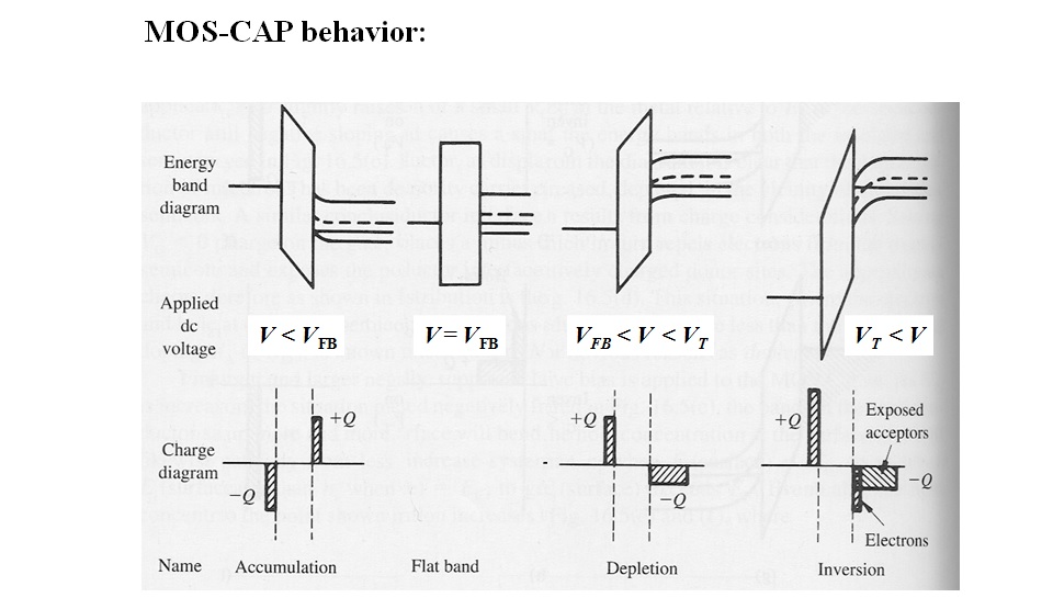
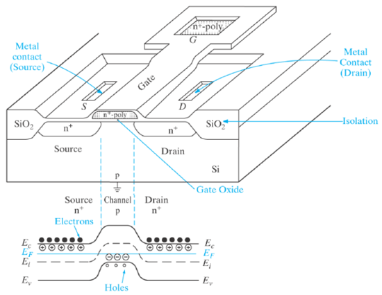
Introduction to Semiconductor Devices 2. To understand the MOSFET we first have to analyze the MOS capacitor which consti-tutes the important gate-channel-substrate structure of the MOSFET. - Energy band diagrams in equilibrium accumulation depletion and inversion modes- MOS capacitor- Charge distributions and electric fields at strong invers.
The energy band diagram for ideal MOS capacitor at thermal equilibrium with zero biased voltage condition is. The MOS capacitor. 000 Recap of MOSFET inversion and modes of operation717 Example.
3-2 MOSFET IV Equation Mobility Calculation ShortLong Channel MOSFET 1552. MOS Capacitor band diagram question. Once the location of Ei is known the conduction and valence bands can be.
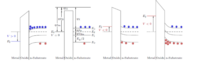
3-4 n-MOSFET Band Diagram. The energy band diagram of the p-type MOS device under inversion condition is shown in Fig. ΦF VT Ln NA ni where VT KTq is thermal voltage.
In a MOS system is the energy offset between metaloxide or semiconductoroxide always the same regardless of the gate voltage. Korea Advanced Institute of Science and TechnologyKAIST. 3-1 Metal-Oxide-Semiconductor Field Effect Transistors MOSFETs 2859.
332 MOSFET Flip-Flop Circuits131 333 Random Access Memory Devices. 3-1 Metal-Oxide-Semiconductor Field Effect Transistors MOSFETs 2859. The electron energy in the channel.
Introduction to Semiconductor Devices 2. As you can see in this. 2 MOSFETs are barrier controlled devices the drain current is controlled by the height of an.

94 Threshold Png

Fetmode T

16 Mosfet Conocimientos Com Ve Mos Capacitors

Ultra Low Temperature Radio Frequency Performance Of Partially Depleted Silicon On Insulator N Type Metal Oxide Semiconductor Field Effect Transistors With Tunnel Diode Body Contact Structures
Electronic Devices Inderjit Singh
Solved Consider An Ideal Pchannel Mosfet A Sketch Energy Band Diagrams For The Mos Capacitor Under The 4 Distinct Biasing Conditions For Each Dia Course Hero

Mosfet Mos Capacitor Band Diagram Question Electrical Engineering Stack Exchange
![]()
Band Diagram Tunnel Field Effect Transistor Mosfet Png 1753x1071px Diagram Area Band Diagram Electronic Band Structure
Fermi Band Diagram In Mos Devices By Sukhanshu Dukare Medium

Energy Band Diagram For The Three Possible Operation Regimes Of The Download High Resolution Scientific Diagram
A Quasi Ballistic Drain Current Charge And Capacitance Model With Positional Carrier Scattering Dependency Valid For Symmetric Dg Mosfets In Nanoscale Regime Nano Convergence Full Text
2 Energy Band Diagrams Of The Two Dominant Types Of Mos Capacitors Download Scientific Diagram

Metal Oxide And Semiconductor Materials In Contact Forming Mos Systems
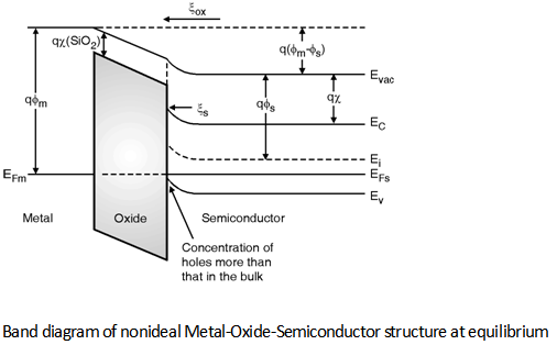
Band Diagram Of Nonideal Mos Digital Cmos Design Electronics Tutorial

Energy Band Diagram
6 4 The Metal Insulator Semiconductor Fet Mosfet 1 네이버 블로그
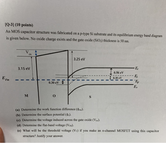
Solved Q 3 10 Points An Mos Capacitor Structure Was Chegg Com